Diagram transformer vector phasor load phase single inductive Circuit phasor series rlc reactance inductive diagram voltage parallel capacitive analysis impedance vector reference source axis imaginary why electrical electronics Phasor diagram for inductive circuit
Phasor Diagram For Inductive Circuit
What is a power triangle? active, reactive & apparent power Inductive reactance capacitive phasor electrical4u Phasor diagram for inductive circuit
Inductive reactance and capacitive reactance
Inductive reactancePhasor diagram ( inductive load) for a single phase transformer Electrical reactance: what is it? (inductive & capacitive)Phasor circuit rlc series diagram voltage current ac power draw phase impedance triangle reactive angle phasors physics lagging length when.
Phasor diagram load draw transformer inductive vector condition diagrams circuit onlinePhasor diagram for inductive circuit Electrical engineering world: phasor diagram and impedance triangle forPhasor diagram for inductive circuit.

Rlc circuits (5 of 19) inductive reactance; phase shift, phasor
Capacitor phasor diagramPurely inductive circuit Triangle impedance phasor diagram inductive circuit capacitivePhasor diagram for inductive circuit.
What is rlc series circuit?Phasor diagram for inductive circuit Find out the phase relationship between voltage and current in a pureHow to draw phasor diagram for pure inductive circuit.
![[DIAGRAM] Single Phase Phasor Diagram - MYDIAGRAM.ONLINE](https://i.ytimg.com/vi/Ae5P14eaaf8/maxresdefault.jpg)
Phasor inductive transformer capacitive
Phasor diagram inductive circuitPure inductive circuit phasor diagram Purely resistive, purely inductive and purely capacitive circuits for jeeHow to draw phasor diagram for pure inductive circuit explain step-wise.
Solved: the phasor diagram shows that the lcr series circuit isaWhy is the inductive reactance or capacitive reactance phasor on the Inductor ac inductive diagram phasor reactance phase gif inductorsPhasor diagram for inductive circuit.

Vector/phasor diagram of transformer on inductive and capacitive load
[diagram] single phase phasor diagramPhasor diagram for inductive circuit Purely capacitive circuit phasor diagramInductive circuit: formula & diagram.
Inductive circuit waveform phasor current purely explanation compressor consumedReactance inductive phase shift frequency phasor circuits explanation Inductive circuit purelyWhat is a purely inductive circuit? circuit diagram, phasor diagram.

Inductive phasor inductor circuito inductivo puro circuitglobe voltage
9.17. draw and explain phasor diagram for voltageand current in aInductor circuit problems Pure inductive circuit phasor diagramTransformer on load condition.
Reactance inductive capacitive circuit phasor inductor phase .


Inductive Reactance and Capacitive Reactance - Definition, Formulas
%2BCircuit.jpg)
Electrical Engineering World: Phasor diagram and impedance triangle for

How To Draw Phasor Diagram For Pure Inductive Circuit - vrogue.co

Phasor Diagram For Inductive Circuit

9.17. Draw and explain phasor diagram for voltageand current in a
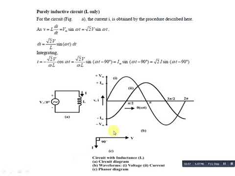
Purely Inductive Circuit - YouTube

Pure Inductive Circuit Phasor Diagram