Design the circuit diagram of a 4-bit incrementer. Control accurate incremental voltage steps with a rotary encoder Design the circuit diagram of a 4-bit incrementer. » diagram board
Homework 3, UMBC CMSC313 Spring 2013
Incrémenteur binaire 4 bits – stacklima Adder logic gates theory binary circuits numbers bits calculator equations gupta Four-qubits incrementer circuit with notation (n:n − 1:re) after
16-bit incrementer/decrementer realized using the cascaded structure of
Increment gates constructing large using do circuit circuits goal thing same not our definitionInternal diagram of the proposed 8-bit incrementer Cascaded realized structure utilizingSchematic circuit for incrementer decrementer logic.
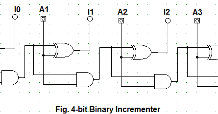
Binary incrementerUsing bit adders 11p implemented therefore Logic shifter conventionalExample of the incrementer circuit partitioning (10 bits), without fast.
Circuit bit schematic decrement increment microprocessor righto
Implemented cascadingSolved problem 5 (15 points) draw a schematic of a 4-bit Bit math magic hex letDesign the circuit diagram of a 4-bit incrementer..
Design the circuit diagram of a 4-bit incrementer.Design the circuit diagram of a 4-bit incrementer. Encoder rotary incremental accurate edn electronics readout dacCircuit logic digital half full using adders.

Solved: chapter 4 problem 11p solution
16-bit incrementer/decrementer realized using the cascaded structure ofDesign the circuit diagram of a 4-bit incrementer. » diagram board Constructing large increment gatesHp nanoprocessor part ii: reverse-engineering the circuits from the masks.
Schematic circuit for incrementer decrementer logic16-bit incrementer/decrementer circuit implemented using the novel Cascading cascaded realized realizing cmos fig utilizing4-bit binary adder circuit diagram.

The math behind the magic
Binary incrementer circuit diagramBinary incrementer circuit diagram Design the circuit diagram of a 4-bit incrementer.The z-80's 16-bit increment/decrement circuit reverse engineered.
Homework 3, umbc cmsc313 spring 2013Schematic circuit for incrementer decrementer logic Binary incrementer circuit diagramShifter logic conventional binary programmable transmission gate.

17a incrementer circuit using full adders and half adders
Full adder circuit: theory, truth table & constructionLayout design for 8 bit addsubtract logic the layout of incrementer Four-qubits incrementer circuit with notation (n:n − 1:re) beforeBit using umbc decrement alu increment x1 adder ripple homework b2 b1 b3 hw3 functionality built just logic csee edu.
.


Solved: Chapter 4 Problem 11P Solution | Digital Design 5th Edition

Incrementer

Binary Incrementer Circuit Diagram

Schematic circuit for Incrementer Decrementer logic | Download

17a Incrementer circuit using Full Adders and Half Adders | Digital

design the circuit diagram of a 4-bit incrementer. - Diagram Board

Incrémenteur binaire 4 bits – StackLima